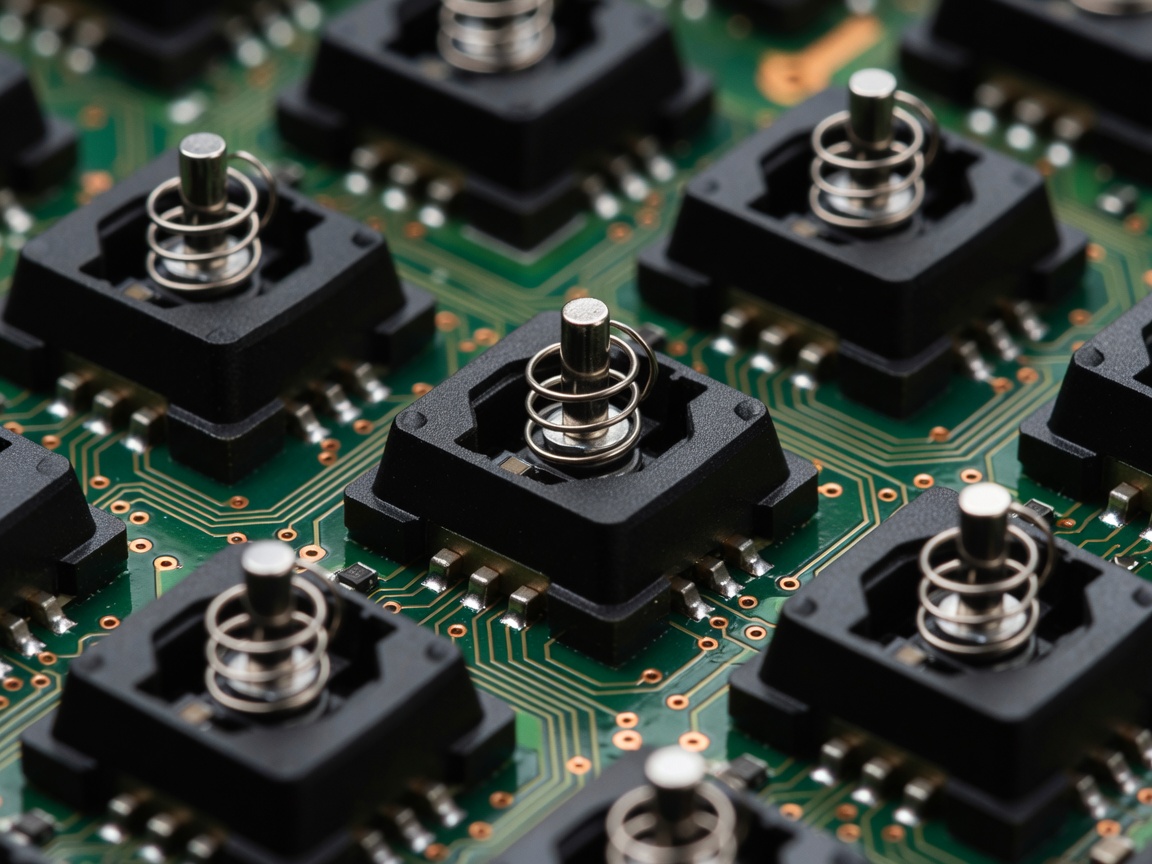
1. The Mechanical Limitation of Traditional Metal Leaf Contacts
Traditional mechanical keyboards rely on physical leaf spring contacts. When a key stem is pressed downward, plastic ramps push two flexible copper alloy leaves together, completing an electrical loop monitored by a microcontroller. While mechanically robust, this approach imposes fundamental timing limits known as contact chatter or debounce delay.
When copper leaves strike each other at high velocity, they physically bounce microscopically before settling into continuous conductance. To prevent a single keystroke from registering as multiple rapid presses, keyboard firmware developers implement a debounce window—typically 5 to 15 milliseconds—during which the controller ignores state shifts. While algorithmic noise filtering has improved, traditional switches remain mechanically bound to fixed actuation thresholds (typically 1.5mm to 2.0mm) and reset thresholds higher up the stroke path.
2. Operating Principles of Hall-Effect Magnetic Sensing
Hall-effect analog switches break this paradigm by replacing metallic friction contacts with magnetic proximity sensors. A small permanent neodymium magnet is embedded within the moving key stem. Direct-mounted to the keyboard printed circuit board (PCB) beneath each switch sits an analog Hall-effect sensor or magneto-resistive element.
As the key stem descends, the magnetic field strength passing through the semiconductor sensor increases proportionally to the travel distance. The sensor outputs an analog voltage curve that directly maps the absolute physical position of the key in real time. Because there are no physical electrical contacts striking together, contact chatter is physically nonexistent, completely eliminating firmware debounce intervals.
3. Continuous Rapid Trigger Mechanics
The defining competitive advantage of analog magnetic keyboards is the implementation of Dynamic Actuation and Rapid Trigger firmware routines. In conventional switches, once actuated at 2.0mm, a player must release the key upward past the 1.5mm reset point before it can be re-pressed to initiate another stroke. This deadzone creates significant physical latency during counter-strafing in competitive tactical shooters.
With Rapid Trigger, the firmware does not look for static coordinate crossings. Instead, it tracks the real-time velocity vector of the stem. The instant the key starts traveling upward by as little as 0.1mm, the firmware de-actuates the key instantly. Conversely, the moment downward motion resumes by 0.1mm, it triggers anew, regardless of whether the key is near the top or bottom of its 4.0mm travel path.
Actuation Architecture Comparison
| Feature Dimension | Traditional Mechanical | Hall-Effect Analog | Optical Mechanical |
|---|---|---|---|
| Contact Method | Copper Leaf Friction | Magnetic Proximity (Hall) | Infrared Light Barrier |
| Debounce Latency | 3ms to 12ms Algorithm | 0ms (Analog Filtered) | 0.1ms to 0.5ms |
| Actuation Config | Fixed (Factory Leaf) | 0.1mm – 4.0mm Variable | Fixed or Dual-Point |
| Rapid Trigger Mode | Unsupported | Native Sub-Millimeter | Limited Emulation |
| Environmental Vulnerability | Oxidation & Dust | External Magnetic Fields | Dust in Optical Chamber |
4. PCB Topologies and Structural Mounting Types
The structural chassis directly affects both acoustic resonance and switch stability. In Hall-effect keyboards, tolerances must be maintained within tenths of a millimeter across the entire PCB assembly, as any plate deflection could alter the sensor-to-magnet distance calibration:
- Tray Mount: Screwed directly into standoffs within the bottom case. Rigid but prone to uneven acoustic feedback and localized stiffness around screw columns.
- Gasket Mount: Isolates the switch plate and PCB assembly between silicone or Poron foam strips. Provides softer bottom-out feel, though excessive flex requires robust dynamic recalibration firmware to maintain rapid trigger accuracy.
- Integrated Top Mount: The plate is machined directly into the upper case frame. Offers maximum structural rigidity, ensuring that magnet travel distance corresponds precisely with calibrated sensor thresholds.
5. Firmware Polling Pipelines & Considerations
Sampling 61 to 108 analog sensors at rates sufficient to sustain sub-millimeter precision requires high-speed microcontrollers. Leading boards utilize ARM Cortex-M4 or high-clock RISC-V cores running at 8,000Hz (0.125ms) polling intervals to prevent internal scan buffering. However, thermal drift remains an engineering hurdle: changes in room temperature affect permanent magnets and sensor gain, necessitating automated temperature compensation algorithms to prevent ghost inputs over extended sessions.